

Company profile
During the procurement and on-site maintenance of transformers, the tank is often viewed merely as an "outer shell"-as long as it holds oil, doesn't leak, and has a decent paint job, it is often considered sufficient. However, in practice, many issues arise precisely from this "shell": oil seepage at flanges, pinholes in welds, cracks at the base of cooling fins, deformation during transport, uneven mounting surfaces for bushings, or paint blistering and peeling. A transformer tank is not an isolated iron box; it plays an integral role in heat dissipation, sealing, mechanical support, and the arrangement of external interfaces. Examining these specific technical challenges is far more useful than speaking in vague terms about the tank's "importance."
What structural functions does the tank actually serve?
It is not a static container, but rather the structural interface platform for the entire piece of equipment.
The tank must first house the insulating oil and the internal active parts (the core and windings), providing sufficient clearance for insulation and space for oil circulation.
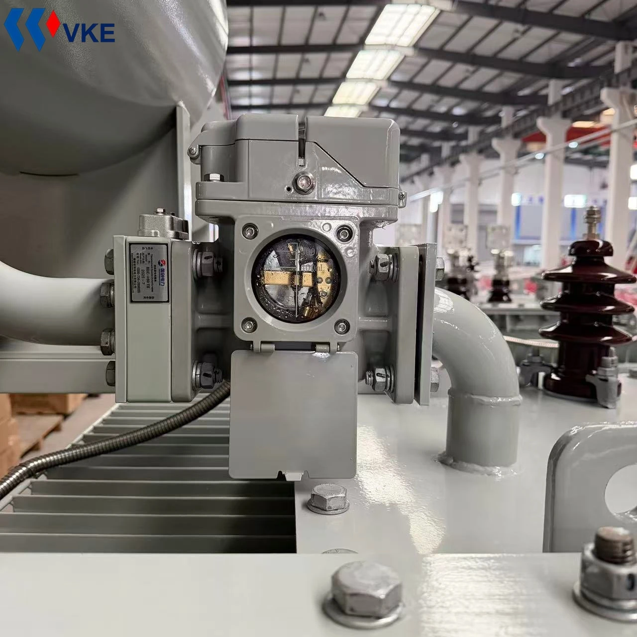
The tank cover must support external components such as bushings, tap changers, connections for the oil conservator, and the gas relay, while the tank walls must accommodate cooling elements, lifting lugs, valves, and grounding terminals.
The tank must also withstand negative pressure during vacuum oil-filling, positive pressure during operation, mechanical shocks during transport, and lifting stresses during installation.
The choice of tank type is not arbitrary
When distribution transformers are installed outdoors-whether on poles, platforms, or the ground-factors such as precipitation, condensation, temperature fluctuations, and corrosion resistance must be considered. Issues like water accumulation at the base of the tank or paint blistering are rarely just a matter of poor coating; they are typically the result of flaws in structural drainage and sealing design.
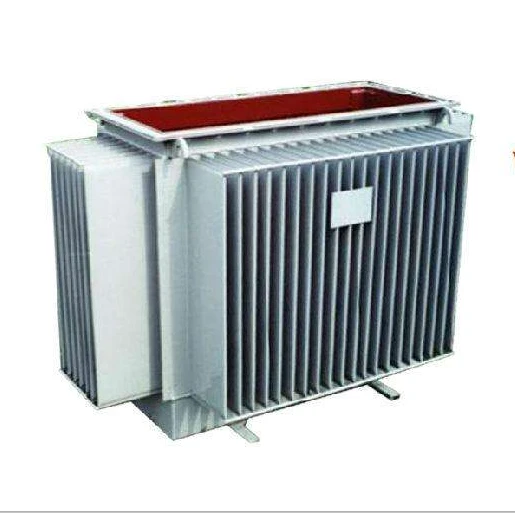
Small distribution transformers typically utilize flat-walled or corrugated tanks. In the latter, the corrugated panels themselves serve as heat-dissipation surfaces; this compact design is ideal for installations where space is limited.
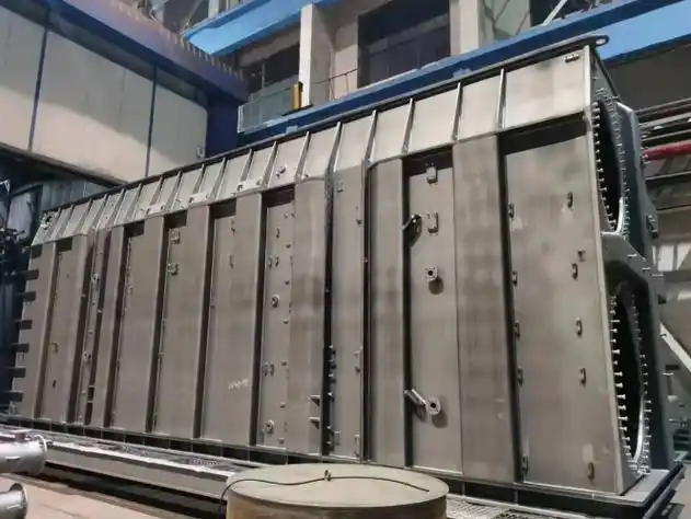
For units with higher capacities or greater cooling requirements, tubular or radiator-fin tanks are common. These designs increase the effective cooling surface area through tubes or fins, relying on the natural circulation of the oil to transport heat to the tank walls.
In fully sealed, oil-immersed transformers, the tank, along with its seals, flanges, and valves, forms a permanently enclosed oil system. The integrity of the sealing design and the quality of the welding are the primary factors that determine whether slow oil leakage will occur during operation.
Welding and Sealing: The Devil Is in the Details
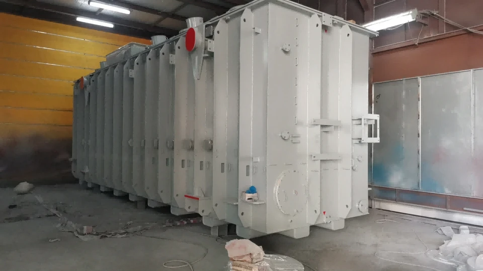
While the manufacturing of an oil tank may appear to be a simple matter of sheet metal fabrication and welding, the real challenge lies in controlling deformation and preventing leaks. Dimensional inaccuracies in steel plate cutting, improper welding sequences, warping of flanges after welding, over-grinding of weld seams, or scratches on sealing surfaces-all these can create hidden risks for future leaks. Before leaving the factory, tanks typically undergo pressure or airtightness tests to verify the integrity of weld seams, flanges, valve connections, and bushing mounting surfaces.
The material and compression of the gasket, as well as the bolt-tightening sequence, are equally critical. Excessive compression can cause permanent deformation of the gasket, while uneven compression can lead to localized gaps. Instances where a unit begins leaking oil shortly after installation are often not due to poor gasket quality, but rather to uneven flange surfaces, improper bolt-tightening sequences, or damage to connection points during transport.

Heat Dissipation and Oil Circulation: Beyond Just Surface Area
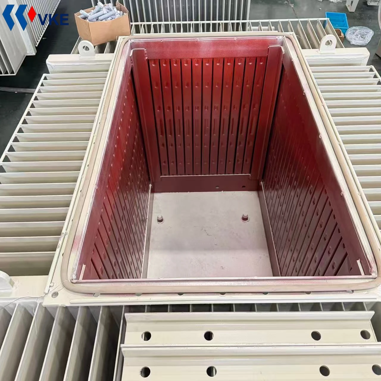
More cooling components do not necessarily equate to better performance. The arrangement of cooling tubes or fins must align with the oil flow path to prevent "dead zones" where oil stagnates. If the spacing between fins is too narrow, dust accumulation increases, making cleaning difficult and degrading cooling efficiency over time-a common issue for equipment installed outdoors. In corrugated-wall tanks, the corrugations serve both as cooling surfaces and as a means of elastic compensation; therefore, the design must account for thermal expansion/contraction and mechanical fatigue.
Furthermore, cooling designs cannot be standardized across all applications-a pole-mounted transformer and a ground-mounted pad-mounted transformer, for instance, operate in different ventilation environments and require tailored thermal designs. Relying solely on "total cooling surface area" as a procurement metric-without considering oil flow dynamics, fin spacing, corrosion protection, and ease of cleaning-can lead to significant discrepancies in actual operational performance.
Transportation and On-Site Installation:
Critical Stages for Oil Tank Issues
If oil traces are discovered, it is essential to determine whether the leak originates from a gasket, a weld seam,
or a loose connection, as each requires a different corrective approach.
During transport, oil tanks are subjected to vibrations, lifting forces, and potential impacts. Inadequate design can lead to localized deformation of the tank walls or cracking of the weld seams.
Upon arrival at the installation site, issues such as an uneven foundation, forced alignment of flanges, unclean sealing surfaces, or tightening bolts all at once can cause a perfectly sound tank to develop leaks once it is put into operation.
During routine operation and maintenance, inspecting flange bases, valve connections, radiator weld seams, and bushing mounting surfaces is far more meaningful than simply checking the oil level.
When procuring, consider asking these specific questions:
Asking these questions provides a better insight into a manufacturer's attention to detail regarding oil tanks than simply comparing price quotes.
What standards are used to determine the steel plate thickness for the tank walls and cover, as well as the layout of the reinforcing ribs? Are there specific requirements for controlling tank deformation?
01
How are the flange sealing surfaces machined and inspected? Are there documented procedures for gasket material, compression levels, and the sequence for tightening bolts?
02
What type of cooling elements are used-tubular, plate-type, or corrugated? How are the spacing between the cooling elements and the anti-corrosion coating tailored to the installation environment?
03
What types of non-destructive testing or leak testing are performed on the welds? How is the hold time for pressure testing determined?
04
Are instructions for securing the unit during transport and for on-site installation provided with the shipment? How is the flatness of the bushing mounting surfaces ensured?
05
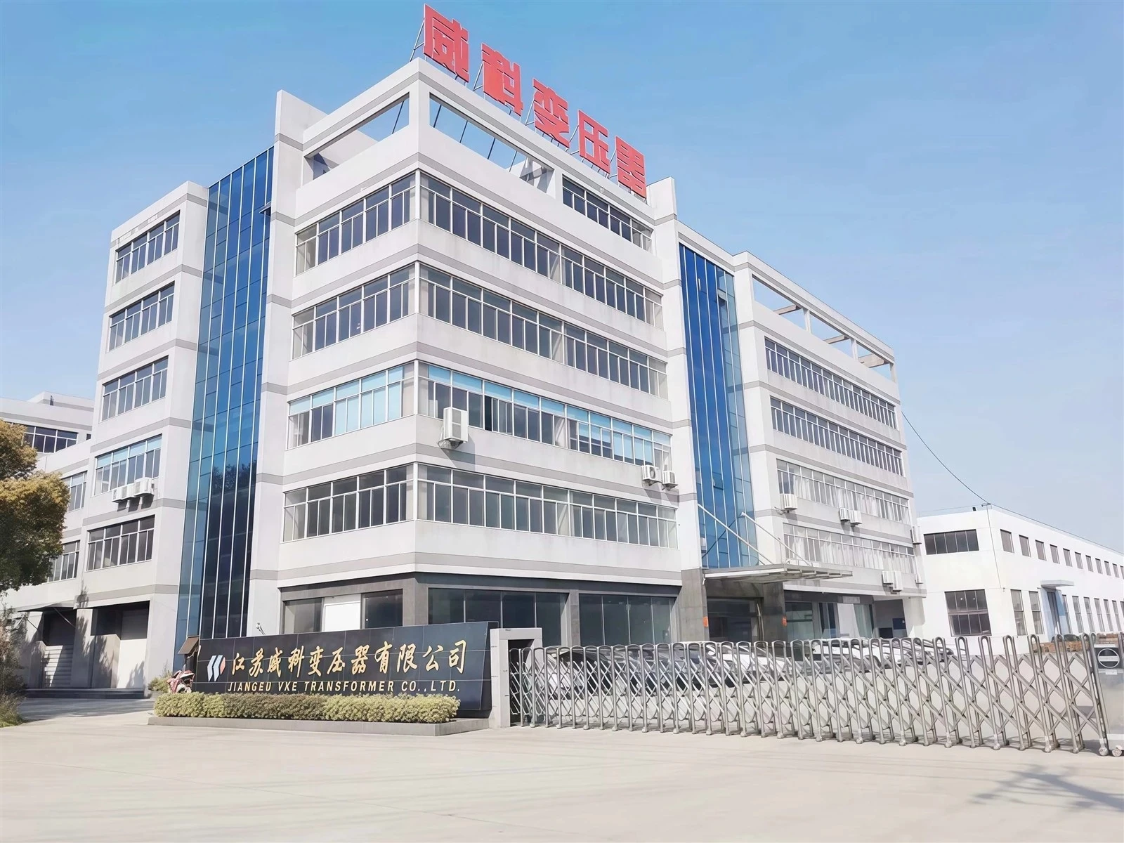
Jiangsu VKE Transformer Co., Ltd. has been engaged in transformer manufacturing since 2003. With two production facilities and an annual capacity of 6,000 MVA, our product range includes oil-immersed transformers, dry-type transformers, pole-mounted transformers, pad-mounted transformers, and compact substations. Our standard factory-exit procedures encompass tank welding, seal testing, painting, and pre-oil-filling inspections.

One-stop Transformer Manufacturing Factory in China
If you are currently evaluating suppliers, we invite you to visit our facilities in person to observe our tank welding, flange machining, seal testing, and painting processes. You are also welcome to share your specific requirements-such as capacity, voltage rating, and installation environment-so that we may provide a tailored quotation based on your exact specifications.